Table of Contents
Introduction
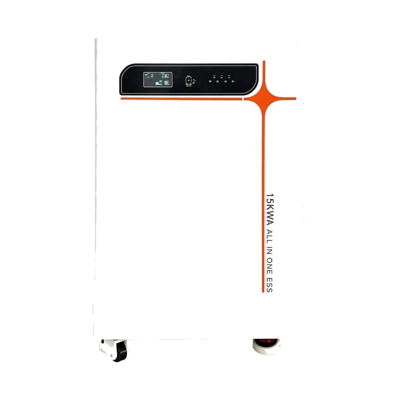
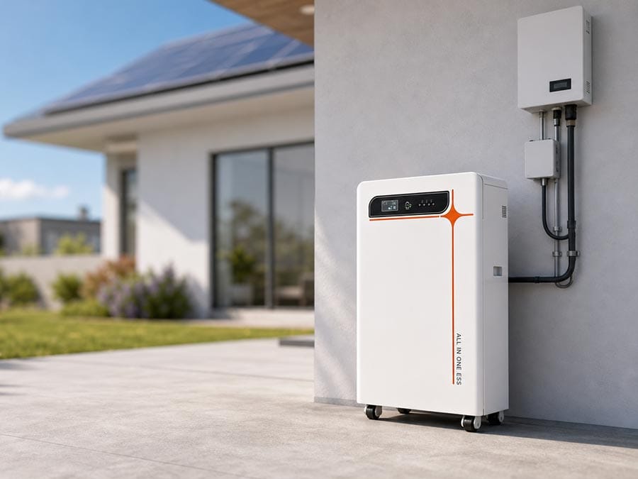
An Energy Storage All-In-One Machine is designed to solve a problem that becomes increasingly important as energy systems grow more complex: how to make batteries, power conversion, photovoltaic input, protection, communication, and control operate as one coordinated product instead of a collection of separately selected components.
That distinction matters. Putting a battery and inverter inside the same cabinet does not automatically create a well-integrated storage system. The electrical interfaces must be matched, battery information needs to reach the power-control layer correctly, heat generated by different components must be managed without creating unfavorable conditions elsewhere in the enclosure, and protection functions must respond in a predictable order when abnormal conditions occur.
For installers, project developers, distributors, and OEM/ODM teams, the quality of an Energy Storage All-In-One Machine should therefore be evaluated through integration quality rather than component quantity. A compact enclosure is useful, but only when it also simplifies wiring, commissioning, maintenance, fault diagnosis, and long-term operation.
This article examines eight design checks that help determine whether an all-in-one energy storage platform has been engineered as a complete product. The focus is deliberately different from basic battery sizing or Hybrid Inverter selection: it looks at the internal interfaces that turn several energy components into one practical machine.
What Makes an Energy Storage All-In-One Machine Different?
A conventional storage project may use a separate battery cabinet, inverter, photovoltaic controller, protection equipment, communication gateway, and monitoring system. Each component can perform its own function correctly, but the project team is responsible for ensuring that all of those interfaces work together.
An Energy Storage All-In-One Machine moves much of that integration into the product-development stage. Battery voltage, inverter requirements, BMS communication, internal conductors, protection devices, control logic, enclosure layout, and monitoring can be designed around one defined architecture.
The broader field of energy storage covers many technologies, but an integrated electrochemical system is particularly dependent on coordinated electronics and software because energy must move through several controlled stages before it becomes useful power for connected loads.
The main value of an all-in-one design is therefore not simply fewer external components. It is fewer uncertain interfaces. When the internal architecture is properly engineered, installation becomes more predictable because the most important battery-to-inverter, control, and protection relationships have already been established before the equipment reaches the project site.
Design Check 1: Is the Battery Properly Matched to the Inverter?
Battery capacity and inverter output describe different capabilities.
The battery determines how much energy can be stored, while the inverter determines how quickly that stored energy can be delivered to AC loads. A system may contain substantial battery capacity and still be unable to support a large simultaneous load if inverter output or battery discharge current is insufficient.
An integrated system should therefore be designed around the complete DC power path. Battery voltage, normal operating range, discharge-current limit, inverter input requirement, conductor size, BMS limits, and protection settings should all support the same intended output.
This becomes particularly important during short periods of high demand. Some loads require considerably more power when starting than during steady operation. If the inverter can produce the required surge but the battery or BMS cannot supply the corresponding current, the system may still reach a protective limit.
A strong Energy Storage All-In-One Machine avoids this mismatch by treating the battery and inverter as two sides of one power system rather than independent specifications placed in the same enclosure.
Design Check 2: Are the Internal Energy Paths Clearly Defined?
An integrated storage machine may receive energy from photovoltaic generation, an external AC source, or another supported input while supplying loads and charging the battery according to its operating mode.
The system therefore needs clearly defined power-flow priorities.
When photovoltaic generation exceeds immediate load demand, the machine may direct the surplus toward battery charging. When solar input falls, stored energy may support the load. During another operating condition, the system may preserve battery capacity because a backup reserve has been configured.
The important engineering question is how these decisions are made.
A mature control architecture should prevent unnecessary energy circulation between subsystems. For example, the machine should not repeatedly move energy through avoidable conversion paths simply because several sources are available at the same time.
The Energy Storage All-In-One Machine concept is most useful when photovoltaic input, battery storage, power conversion, and load supply are coordinated as one energy path instead of being treated as independent devices connected after installation.
For project teams, understanding these operating priorities is more valuable than seeing a long list of available modes without knowing how they interact.
Design Check 3: Does the BMS Influence Real-Time Power Control?
The Battery Management System monitors battery conditions, but its role should extend beyond shutting the battery down when a limit is exceeded.
Battery capability changes during operation. State of charge, cell voltage, temperature, current, and internal conditions can influence how much charging or discharge power should be permitted at a given moment.
A well-integrated Energy Storage All-In-One Machine uses this information actively.
If the BMS reports that charging current should be reduced, the inverter or charging stage should respond before the battery reaches a hard protection threshold. If discharge capability changes because of battery conditions, system output should be adjusted accordingly rather than waiting for an emergency shutdown.
This creates a smoother relationship between protection and normal operation.
Communication quality matters as much as the physical interface. The system needs reliable data exchange, clear fault states, appropriate update timing, and defined behavior if communication is lost.
An all-in-one product has an advantage here because the battery, BMS, and inverter communication can be developed and validated together instead of relying entirely on third-party compatibility in the field.
Design Check 4: Has Thermal Zoning Been Considered Inside the Cabinet?
Integration saves space, but it also places heat-generating components closer together.
Battery cells, switching devices, magnetic components, busbars, relays, protection equipment, and internal wiring all produce some heat during operation. Their thermal requirements are not identical.
Power electronics may generate concentrated heat during high output, while battery longevity benefits from maintaining a stable thermal environment. If hot air from the inverter section is allowed to flow directly through the battery area, the compact architecture can create a disadvantage rather than a benefit.
Good enclosure design therefore uses thermal zoning.
The physical layout should consider where heat originates, where cooling air enters, how it moves through the enclosure, and where it exits. Temperature sensors should represent meaningful thermal conditions instead of being located only where installation is convenient.
Internal spacing also matters because airflow channels can become restricted when conductors, protective devices, or mechanical supports are added late in development.
A well-designed Energy Storage All-In-One Machine should maintain sufficient thermal margin during sustained operation without depending on frequent protective derating as part of normal use.
Design Check 5: Are Protection Functions Coordinated Rather Than Duplicated?
An integrated storage system may contain several layers of protection.
The BMS can monitor battery conditions. The inverter can detect abnormal input or output behavior. Hardware protection can interrupt excessive current. Temperature sensors can identify overheating. Communication software can detect missing or inconsistent device information.
Having multiple protection layers is valuable, but only if their responsibilities are clear.
If every subsystem reacts independently to the same event, one original fault may produce several secondary shutdowns and alarms. This makes diagnosis more difficult and can obscure the actual cause.
A stronger architecture defines a response hierarchy.
Some conditions may justify reducing power while the system remains operational. Others may require one subsystem to stop. More serious conditions may require complete electrical isolation.
The control system should know which response is appropriate instead of treating every warning as an identical failure.
For maintenance teams, this produces clearer fault records and reduces the risk of replacing healthy components simply because they generated secondary alarms after another subsystem failed first.
Design Check 6: Can the Machine Be Serviced Without Dismantling Everything?
Integration can improve installation but create maintenance problems if serviceability is considered too late.
A compact enclosure may contain the battery, inverter, control board, communication hardware, cooling components, protection devices, and electrical terminals within a limited space. If the internal layout is optimized only for factory assembly, technicians may struggle to access commonly serviced components later.
Service paths should therefore be part of mechanical design.
Electrical terminals need adequate access for inspection. Communication boards and protection devices should be identifiable. Cooling components should be reachable without removing unrelated high-power assemblies. Wiring should have enough organization and flexibility to allow one subsystem to be serviced without disturbing several others.
Software diagnostics should support physical serviceability as well. A fault code is far more useful when it clearly identifies the subsystem a technician can then locate inside the enclosure.
The best all-in-one products are not merely compact. They are compact without making maintenance unnecessarily difficult.
Design Check 7: Has Factory Configuration Reduced On-Site Commissioning Risk?
One of the strongest advantages of an Energy Storage All-In-One Machine is the ability to complete more integration work before installation.
In a system assembled from separate components, the installer may need to configure battery communication, establish inverter settings, verify charging parameters, connect multiple protection devices, and confirm that independent products interpret operating states correctly.
An integrated product can move much of this work into controlled factory configuration and validation.
That does not eliminate commissioning. External photovoltaic input, AC wiring, grounding, load allocation, ventilation, protection coordination, and operating modes still need to be verified at the installation site.
However, internal communication and core component matching should already be established.
This reduces the number of unknown interfaces the installer must diagnose and makes commissioning more focused. Instead of determining whether the battery and inverter can communicate at all, the installer can concentrate on whether the complete machine has been configured correctly for the application.
This difference can make integrated architecture especially useful in projects where repeatable installation is important.
Design Check 8: Can the System Be Updated Without Creating New Compatibility Problems?
Energy storage products increasingly depend on firmware.
The BMS, inverter, display, communication controller, and energy-management logic may all contain software that influences system behavior.
This creates long-term flexibility, but it also creates an integration responsibility.
Updating one subsystem should not unintentionally change how another subsystem interprets data or commands. Communication structures, protection thresholds, operating modes, and display behavior need version control.
A mature Energy Storage All-In-One Machine should therefore have a clear software architecture in which internal interfaces remain controlled as firmware evolves.
This is particularly important for OEM/ODM projects because customized functions may introduce new software dependencies. A change requested for the user interface can affect control logic, while a BMS update can influence inverter charging behavior.
Software validation should consequently include the complete machine rather than only the component whose firmware was modified.
Integrated hardware creates the physical product, but coordinated firmware determines how that product continues to behave over time.
The Eight Integration Checks at a Glance
The following table summarizes the areas that matter most when evaluating an Energy Storage All-In-One Machine as a complete system.
| Design Check | Main Integration Risk | What Good Design Should Achieve |
|---|---|---|
| Battery-inverter matching | Energy capacity and output power do not align | Stable power within battery and inverter limits |
| Energy-flow architecture | Inefficient or conflicting operating modes | Clear routing between PV, battery and loads |
| BMS coordination | Hard protection occurs before control adapts | Dynamic charge and discharge adjustment |
| Thermal zoning | Inverter heat affects battery conditions | Controlled airflow and adequate thermal margin |
| Protection hierarchy | Multiple alarms hide the original fault | Predictable staged protection response |
| Serviceability | Compact enclosure becomes difficult to maintain | Accessible components and clear diagnostics |
| Factory configuration | Excessive integration work is left to installers | Repeatable internal setup before deployment |
| Firmware coordination | Updates create subsystem incompatibility | Controlled software interfaces and validation |
The value of the table is not in treating these checks independently. They influence one another. Increasing inverter output affects battery current and heat. Reducing cabinet size changes airflow and service access. Updating protection logic can change both BMS and inverter behavior. Integration quality comes from managing these relationships together.
Why EMC Becomes More Important in an Integrated Machine
Combining power electronics, battery monitoring, communication hardware, and control circuits in one enclosure creates an electrically demanding environment.
High-frequency switching inside the inverter can generate electromagnetic noise, while BMS sensing and communication circuits work with comparatively low-level signals. Poor layout can allow one subsystem to interfere with another even though both work correctly when tested separately.
Cable routing, grounding, shielding, PCB placement, enclosure bonding, and separation between power and signal wiring should therefore be considered during mechanical and electrical design.
This is particularly important for communication stability.
An intermittent data problem may appear to be a firmware issue when the underlying cause is electrical interference that occurs only during high inverter output.
Testing should therefore include operation under realistic power conditions rather than only verifying communication while the system is idle.
An all-in-one architecture makes EMC design more demanding, but it also allows the manufacturer to validate the complete internal arrangement as one product before deployment.
Why Installation Simplicity Should Not Hide System Requirements
All-in-one equipment is often easier to install because major subsystems are pre-integrated, but that should not create the impression that system engineering is unnecessary.
Photovoltaic input still needs to remain within the permitted electrical range. External conductors and protection devices need appropriate sizing. The installation environment must provide suitable ventilation. Connected loads should remain within inverter capability, and backup circuits need to reflect the intended operating strategy.
The advantage is that fewer critical relationships are left unresolved.
Instead of designing battery-to-inverter wiring from scratch, the installer can focus on the interfaces between the finished machine and the surrounding energy system.
This is an important distinction.
A good Energy Storage All-In-One Machine simplifies integration without hiding technical boundaries. Product documentation should make those boundaries clear so installers understand both what has already been engineered internally and what still needs to be verified externally.
Monitoring Should Explain the Energy System, Not Just Display Battery Percentage
A battery percentage alone cannot explain how an integrated energy storage machine is performing.
Useful monitoring should help users understand where energy is coming from, where it is going, and whether any subsystem is operating unusually.
For example, a battery that remains at a low state of charge may not indicate a battery problem if photovoltaic generation has been weak and loads have been high. Similarly, reduced output may be intentional if the BMS has temporarily limited discharge capability because of operating conditions.
Displaying energy flow provides context.
Historical operating data can add even more value. Repeated high inverter temperature, unusual state-of-charge behavior, frequent backup transitions, or recurring communication warnings can reveal patterns that are difficult to identify from live status alone.
For maintenance teams, useful monitoring shortens diagnosis because it connects a visible symptom with the operating conditions that occurred before it.
An integrated machine already contains many internal data sources. The monitoring design should turn that information into understandable operating insight rather than simply exposing more numbers.
How an All-In-One Machine Differs From Separate Battery and Inverter Systems
Separate systems and integrated systems can both be technically effective, but they shift responsibility to different stages of the project.
A separate architecture provides greater flexibility to select batteries, inverters, controllers, and enclosures independently. That can be useful where the project requires a very specific combination of components.
The trade-off is additional interface validation.
Communication compatibility, operating voltage, charge limits, discharge limits, protection coordination, wiring, and mechanical installation may need to be verified across products that were not originally developed as one platform.
An Energy Storage All-In-One Machine moves more of those decisions into product engineering.
This can improve installation repeatability and simplify system commissioning, particularly where the same storage architecture will be deployed across multiple similar applications.
The decision should therefore be based on integration requirements rather than assuming one architecture is universally superior.
The most important question is where the project benefits most from flexibility and where it benefits more from pre-engineered compatibility.
What OEM and ODM Projects Should Define Before Development
A customized all-in-one storage project should begin with functional requirements rather than exterior appearance.
The development team needs to understand expected battery capacity, inverter power, photovoltaic input, load profile, backup requirements, communication, installation environment, thermal conditions, monitoring functions, and future expansion expectations.
Only after those requirements are clear should enclosure dimensions and user-interface design be finalized.
This order matters because mechanical customization can affect technical performance. Reducing cabinet depth may limit airflow. Changing internal component positions can influence electromagnetic behavior. Moving connectors can alter conductor length or service accessibility.
Software customization needs the same discipline.
Changes to energy priorities, backup reserve, charging behavior, or user settings should be evaluated against BMS limits and inverter operation rather than implemented as isolated interface features.
A high-quality OEM/ODM Energy Storage All-In-One Machine is therefore a coordinated hardware-and-software development project, not a standard storage system with a different outer shell.
How to Validate the Machine Before Deployment

Validation should examine the complete product under conditions that reproduce real energy movement.
A system should be tested while charging, discharging, operating photovoltaic input, supplying different load levels, transferring between power sources, and responding to controlled abnormal conditions.
Thermal stabilization is especially important. A short functional test may confirm that the machine operates, but it may not reveal how battery and inverter temperatures behave after sustained power conversion.
Communication should also be monitored while the inverter is under meaningful load because electrical noise and temperature can influence behavior differently from idle testing.
Protection validation should confirm not merely that the machine shuts down, but that it responds in the intended order and reports a useful cause.
Finally, repeated operation helps reveal intermittent problems that one successful cycle can miss.
A production-ready Energy Storage All-In-One Machine should demonstrate predictable behavior across normal operation, transitions, faults, restart conditions, and sustained use rather than simply completing one charge-and-discharge demonstration.
Conclusion
An Energy Storage All-In-One Machine creates value by reducing uncertainty between the major subsystems of an energy storage installation.
Its real advantage is not that the battery, inverter, photovoltaic charging stage, BMS, protection hardware, and communication electronics occupy one enclosure. The advantage comes when those components have been engineered to share power, data, thermal space, protection logic, and operating priorities as one coordinated platform.
For project teams, the most important evaluation areas are battery-inverter matching, energy-flow control, BMS coordination, thermal zoning, protection hierarchy, maintenance access, factory configuration, and firmware compatibility. These factors determine whether integration genuinely simplifies the system or merely hides complexity inside a cabinet.
A well-designed all-in-one platform should reduce installation uncertainty while remaining transparent enough for technicians to understand, commission, diagnose, and maintain it. When those goals are achieved, the Energy Storage All-In-One Machine becomes a practical foundation for photovoltaic storage, backup operation, and integrated energy management rather than simply a combination of separate components.
FAQ
What is an Energy Storage All-In-One Machine?
An Energy Storage All-In-One Machine integrates key storage functions such as the battery, inverter, BMS, photovoltaic charging control, protection, and communication within one coordinated platform. Its main advantage is reducing compatibility and installation complexity between separate components.
How is an Energy Storage All-In-One Machine different from a separate battery and inverter?
An all-in-one machine pre-integrates important electrical, communication, thermal, and control interfaces. Separate systems provide greater component flexibility but require more project-level compatibility work between the battery, inverter, protection hardware, and communication systems.
Can an Energy Storage All-In-One Machine work with solar panels?
Yes, when the machine includes compatible photovoltaic input and MPPT control. The PV array voltage, current, string configuration, and operating range must still match the machine’s input requirements so solar energy can be supplied to loads or stored correctly.
Why is BMS communication important in an Energy Storage All-In-One Machine?
BMS communication allows the power-control system to understand battery state, temperature, operating limits, and fault conditions. This helps the inverter adjust charging and discharging before the battery reaches hard protection limits and improves overall system coordination.
What should OEM buyers evaluate in an Energy Storage All-In-One Machine?
OEM projects should evaluate battery-inverter matching, PV input, BMS communication, thermal design, protection logic, firmware, enclosure layout, monitoring, maintenance access, and validation procedures so customized hardware and software remain part of one reliable architecture.
Need Help Choosing the Right Energy Storage All-In-One Machine?
If you’re evaluating an Energy Storage All-In-One Machine for photovoltaic storage, backup operation, integrated power management, or a customized OEM/ODM project, the system should be matched to your battery capacity, load profile, PV input, communication, thermal conditions, and operating priorities.
Contact our energy storage specialists to discuss your application requirements and develop an integrated storage solution that fits your power architecture and long-term operating needs.